Some useful information that can be added in a node’s messages, in order to achieve redundancy and strengthen security, is the node’s geographical location.
Geographical information is sometimes used for the basic functioning of routing protocols, such as the DREAM (Distance Routing Effect Algorithm for Mobility) protocol [8]. Nodes using DREAM disseminate information about their position by broadcasting a beacon. Then, a sending node uses a probabilistic model to derive a direction in which the destination node is likely to be found. Packets are forwarded in the chosen direction until they reach the intended destination.
GPSR (Greedy Perimeter Stateless Routing) [84] is similar to DREAM, as the sending node forwards the packet towards the node which is closest to the intended destination. The process repeats until the packet reaches the destination. This is the default functioning mode, called Greedy Forwarding. If the default forwarding mode is not possible in a region (due to lack of nodes close enough to the destination) the protocol routes the packet around the perimeter of that region.
LAR (Location-Aided Routing) [88] is another position-based ad hoc routing protocol. The route discovery mechanism uses message flooding, with an optimization to reduce routing overhead: the node initiating the discovery defines geographically a request zone, and only nodes within the request zone forward the route request message.
The protocols mentioned above are not secured, and use geographical information solely for routing. An example of position-based secured routing protocol is SPAAR (Secure Position Aided Ad hoc Routing) [24]. SPAAR uses public key cryptography to secure hop-by-hop communications, and requires a TTP server for the delivery of certificates. A node A broadcasts its certificate through HELLO messages; one-hop nodes which hear the HELLO respond by sending their certificate, position, and transmission range, encrypted with A’s public key. Upon reception, A verifies that the nodes are truly neighbors, and stores their public key, last known position, and transmission range, in its Neighbor Table. Afterwards, A creates a Neighbor Group key pair and distributes the Neighbor Group decryption key to each neighbor. The Neighbor Group encryption key is used later by A to encrypt all its control messages (RREQs, RREPs and RERRs).
The geographical position can be obtained by using Global Positioning System (GPS) devices embedded into the hardware of each node [38]. The GPS is a satellite-based navigation system that makes possible to know the precise position of the device anywhere on Earth or in Earth orbit; the position is extrapolated from the measures of the distances from the device to a minimum of two satellites. The same GPS facility can be used to provide time synchronization [150].
There exist other solutions which do not require every node to be equipped with a GPS device [138] or which do not use GPS at all [153, 46]. These solutions rely on signals or other feedback from other nodes (e.g. the emission power). However, in a network where the presence of malicious nodes is possible, these solutions cannot be considered safe.
We propose a protocol [131, 132] that enhances security by including and processing the geographical position of the sending node in its control messages. This solution may also be applied to other link state protocols. It is inspired from the work by Hu et al. about packet leashes [67]. Here we assume that the geographical information is obtained by a safe source, like an embedded GPS device.
Several attacks can be thwarted if we possess information about node position, i.e. if every node knows the correct geographical position of any other node in the network. Nodes then compare this geographical data to the received control messages containing topology data (the neighbor and link set). If contradictory information is found, the false control message is detected and discarded.
Besides, the availability of geographical information about nodes in the network opens speculations about possible new features in the standard OLSR, such as improved MPR selection and link breaking forecast. For instance, when two linked nodes are moving in opposite directions (with the distance between the two nodes rapidly increasing), a link break will shortly occur. Therefore, each of the two nodes should not select the other as a MPR. These issues are not in the scope of this thesis, and are not discussed further.
We propose to add a control message called SIGLOC (which stands for SIGnature and LOCalization), based upon the SIGNATURE message presented in Section 5. The SIGLOC message carries an additional GPS Localization field which contains the current geographical position of the sending node, as obtained from the GPS facility, and is included in the signature computation. This field is 32 bits long, that is enough to define the position over an area of more than 4200 square km with a precision of 1 m using Cartesian coordinates; a more efficient representation can also be used.
The format of a SIGLOC message is given in Figure 10.1. All other fields, as well as the mechanisms of signature computation and verification, are the same as for the SIGNATURE message. Similarly, a SIGLOC message is generated and sent along with each HELLO or TC message.
A node informs the other nodes about its current geographical position via this SIGLOC message. The receiving node verifies the correctness of the timestamp and signature as previously specified, and extracts the timestamp and the information relative to the position of the originator node. This data is stored as a tuple
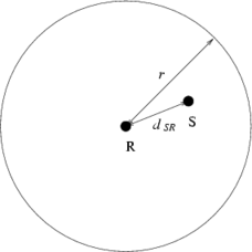
The advantage in knowing the geographical position of nodes is that we can speculate whether communication of a message from a sender node S is likely to be heard or not by a receiver node R. Let pS and pR be the current position of the sender and the receiver and TR the current time according to the receiver’s clock. Also let Δt be the discrepancy in the clocks’ synchronization, Δd the maximum absolute error in position information, vmax the maximum velocity of any node, and rmax the maximum transmission range. Based on the timestamp TS of the sender’s message, we can compute a lower bound on the distance dSR between the sender and the receiver. In fact it must be
 | (10.1) |
as shown in Figure 10.2, where the radius r of the circle is the quantity on the right of the formula: r = ∥pR -pS∥- (TR -TS + Δt) ⋅ 2vmax - Δd. If the (10.1) is not valid, this means that the receiver node is too far from the sender node to be able to hear its transmission; therefore such a transmission is highly suspicious and might be a fake.
An important remark: We denote as sender S the last-hop node that emitted the message received by R; this means that receiver R is 1-hop far away from sender S, i.e. R and S are neighbors. In the case of messages (e.g. TCs) that are being relayed, the sender node S is not the same as the originator node, which is the node that created the message. The address of the originator is contained in the Originator Address field in the HELLO header, and does not change while the packet is relayed around the network. The sender address S is the source address from the IP header of the packet, and is changed, each hop, to the address of the node which is retransmitting the message.
Note that the standard OLSR already defines some checks to be performed at message reception; if the sender S of a TC/MID/HNA message is not a symmetric neighbor of receiver R, the latter must drop the message.
We believe this protocol to be robust against two of the most severe attacks: link spoofing and wormhole.
It may be argued that a compromised node X can forge the GPS information contained in the SIGLOC message. The compromised node can choose any value from scratch; in case the GPS device is tamperproof and supplies geographical data in an encoded format, node X can even record other node’s geographical data, or its old own, and reuse it later. In this case, X could pretend being over time in very different parts of the network, and advertise links with nodes which are in its current part of the network, in order to perform a link spoofing attack.
However, this does not work because node X (as any other node) is always bounded by its maximum velocity vmax. A node that has in its location table the tuple 〈X,pX,TX〉, and receives a SIGLOC message from X carrying a geographical data pX′ and a timestamp TX′, must check if the following condition holds true:
 | (10.2) |
If the (10.2) is not valid, this means that node X pretends to be in a location it could not reach according to its maximum velocity; therefore either pX or pX′ are likely to be false.
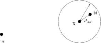
For any communication between a sender and a receiver, the Formula 10.1 must hold valid and this obviously also applies to link state. We can therefore detect the case in which a misbehaving node X falsely advertises a link (in a HELLO message) with the non-neighbor node N, or declares N as a neighbor (in a TC message). In the case of such a false declaration, the (10.1) is in fact not valid with respect to the distance dXN as evaluated by the receiver A of the message (Figure 10.3).
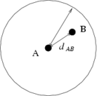
When a message is being maliciously tunneled between legitimate nodes A and B, the Formula 10.1 is not valid with respect to the distance dAB as measured by A (Figure 10.4).
A node generates a SIGLOC message together with any generated HELLO or TC message, with the same specifications of the SIGNATURE message referred in Section 5. The following step is added to the protocol:
When node B receives a SIGLOC and its HELLO/TC from node A, it handles them in the same way it does with a SIGNATURE message, performing the same tests (match of the SIGLOC with the companion HELLO/TC, timestamp validity check, and signature verification). Note that A is the last hop to B, and that we call O the originator of the control message relayed by A. If the control message is a HELLO, then O is surely A because we know HELLOs are not relayed; if the control message is a TC, then O may or may not be A (depending whether A is an MPR or not). The following steps are added to the protocol:
If any of the previous checks fail, node B must stop processing the HELLO/TC and the SIGLOC, and must discard them. Note that this algorithm assumes that B has entries for A, O, and N, in its Position Table; this may not be the case at network initialization. Immediately after network bootstrap, during the first formation of the network, if B lacks the entry needed for the test it should therefore bypass the relevant step.
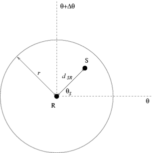
Using a directional antenna instead of an omni introduces additional security. With that, node R can know from which direction the signal is coming; by basing on pR and pS and using simple plane geometry, R can check roughly the correctness of the value pS. Let [θ,Δθ] be the sector of R’s antenna on which the signal is received, and denote with (dSR,θS) the coordinates of S in the polar coordinate system with origin in R. In addition to (10.1), the following condition must also be true:
 | (10.3) |
as shown in Figure 10.5. Formula 10.3 is useful even if the maximum transmission range rmax is not known with precision.
We analyze the consequences of the (10.1). With figures such as v = 60 km/h, TR -TS + Δt = 100 msec, and Δd = 1 meter, we obtain ∥pR -pS∥≤ rmax + 4.333 meter. When rmax is not too small (e.g. rmax > 50 meter), the received packet is necessarily sent from a nearby node within the coverage of the recipient. Therefore, wormhole attacks tunneling such a packet would be difficult to accomplish because the real packet is likely to be heard by the recipient; on the other hand, such an attack would be not very efficient, since the node whose packet is relayed is, most likely, a few hops away. When rmax is small (e.g. 20 meter < rmax < 50 meter) the information given by a directional antenna can be useful, since the sector in which the signal is expected has a limited size.
We assume the use of DSA to generate the signature in the SIGLOC message.
The size of a SIGLOC message is:
SIGLOC: 384 bits
Counting the IP, UDP, and OLSR packet and message headers, the size of a OLSR packet containing a HELLO/TC message and its companion SIGLOC are:
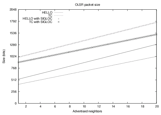
HELLO + SIGLOC (packet): 968 + 40n bits
TC + SIGLOC (packet): 864 + 32n bits
We assume that each HELLO/TC message and its companion SIGLOC message are sent together in the same OLSR packet, and the packet does not contain other messages.
With the assumptions above and those made in Section 5.4.1, and considering a neighborhood of 9 nodes, the flowrate can be evaluated as follows:
OLSR with SIGLOC: 894 bit/sec
Figure 10.6 shows the additional message overhead for the SIGLOC architecture.